Optical terminology

Understanding optical terms enables collaboration, and ultimately results
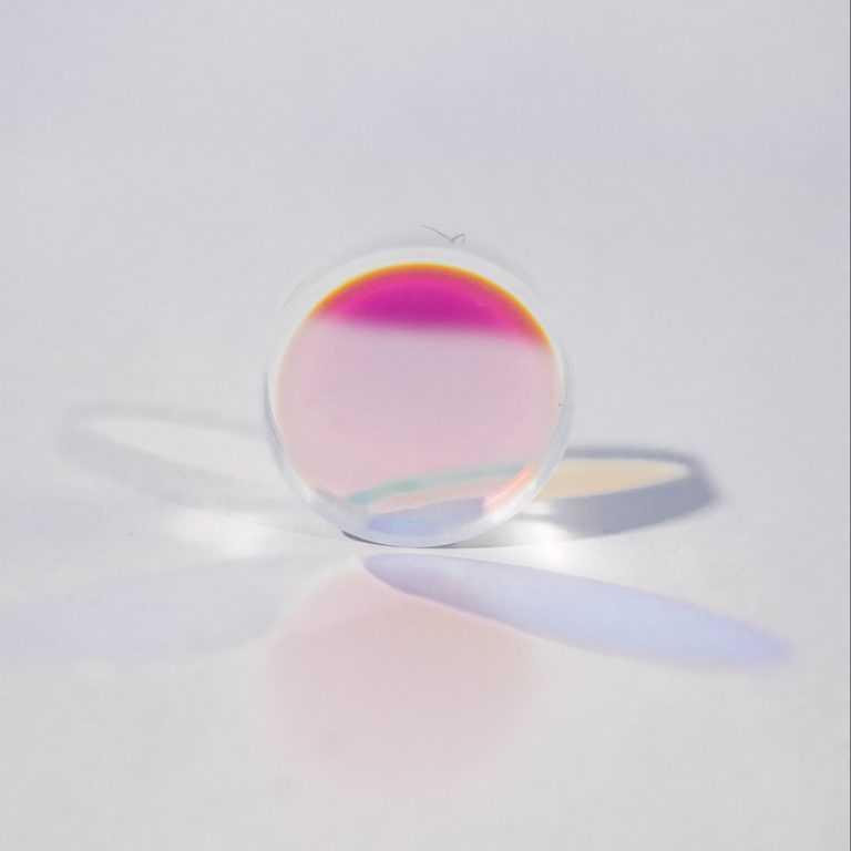
Angle of Incidence
The angle of incidence is defined to be the angle between the direction of propagation of incoming light and a line perpendicular to the component surface.
The performance of most thin film coatings varies. Specifically, the wavelength at which peak reflectivity or transmission occurs may shift, and polarization dependent effects may also become manifest. This should be taken into account when using optic in which the angle of incidence varies over the surface. This happens when components are placed in converging or diverging beams, and with radiused optics, such as lenses.
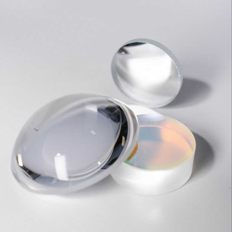
Diameter Tolerances
Dimensional tolerances refer to the allowed variations in the physical dimensions, such as diameter, length, width and thickness, of a finished part. Performing dimensional measurements during part fabrication is usually relatively straightforward, and is accomplished using familiar tools such as calipers, gauges and optical comparators. PFG typically determines radius of curvature on convex or concave parts with an interferometer and a high resolution, optical encoder-based length gauge.
Extinction Ratio
Polarization extinction ratio is the ratio of transmitted power with only p polarized incident light to the transmitted power with only s polarized incident light. PFG determines it by performing separate measurements of s and p polarized light transmittance in our spectrophotometers.
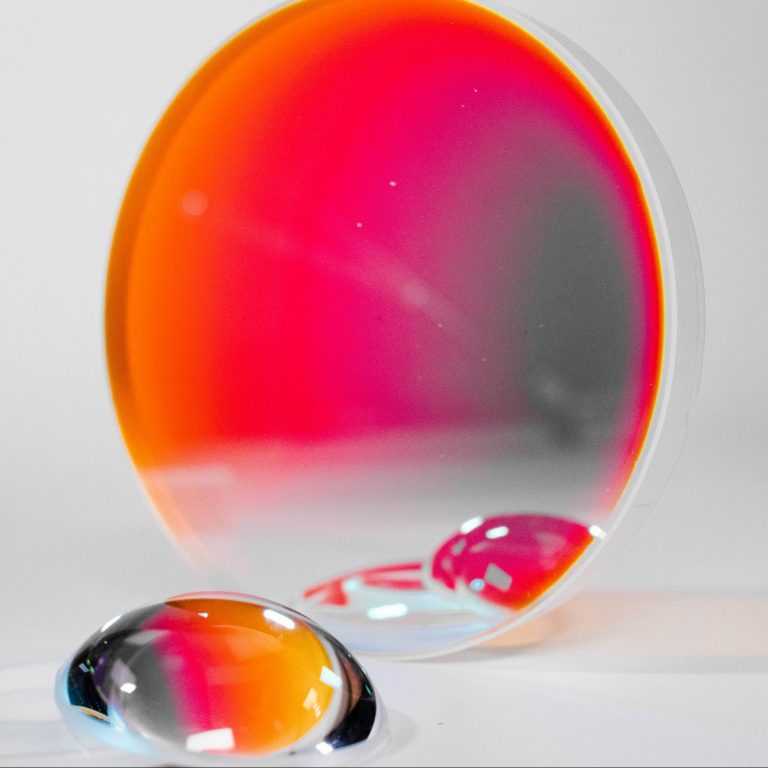
Reflectivity
Reflectance is the ratio of the light flux returned from a surface to the amount of light flux incident on the surface. In the context of precision optical components, the returned light flux specifically refers to specular reflectance (energy contained within the usable returned wavefront), and does not include diffuse reflectance (scattered light).

Transmittance
Surface quality, or scratch and dig (SAD), relates to the number and apparent size of visible defects, typically scratches and pits (called digs), on the part surface. While this may seem straightforward, probably no optical specification causes greater confusion. The problem arises because the assessment of scratches and digs is performed using a purely visual, non-quantitative comparison to a set of standards which conform to the military specification MIL-O-13830. This situation arose because the specification was developed many years before the advent of the laser, when surface quality was primarily a cosmetic, as opposed to a performance, consideration. Scratch-dig is specified by two numbers, such as 40-20. The first relates to the apparent size of scratches, and the second to the apparent size of digs.
Surface Quality
Reflectance is the ratio of the light flux returned from a surface to the amount of light flux incident on the surface. In the context of precision optical components, the returned light flux specifically refers to specular reflectance (energy contained within the usable returned wavefront), and does not include diffuse reflectance (scattered light).
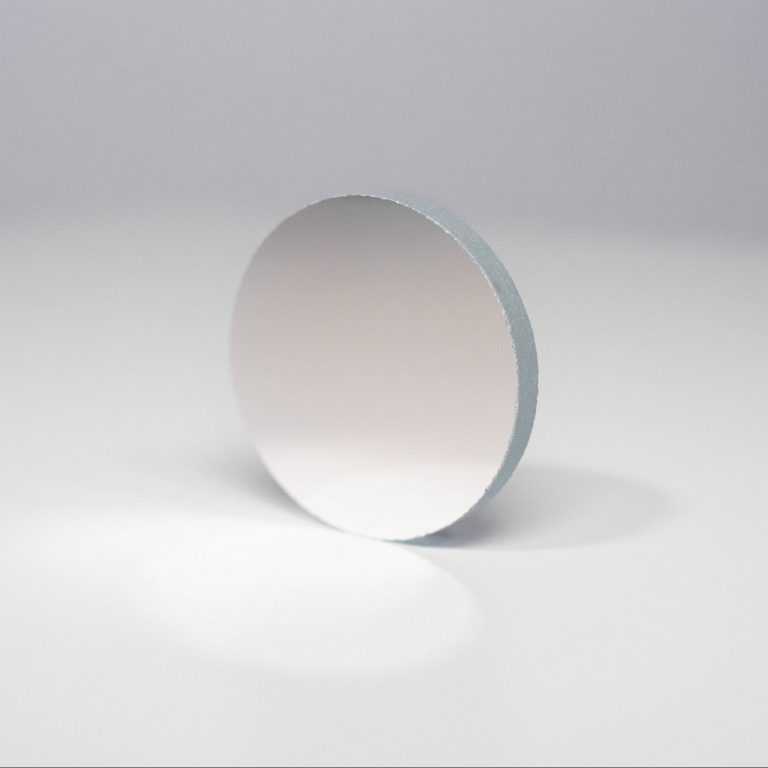
Surface Flatness
For plano parts, surface flatness is defined to be the amount by which the actual part differs from a perfect plane. For radiused parts, two numbers are typically used to specify surface shape. Power is how closely the average part radius matches the specified value, and irregularity is how far the part departs from its ideal shape (e.g. a perfect sphere or cylinder).
Flatness and power/irregularity are typically measured using an interferometer. These instruments use a laser to illuminate the test surface and produce a pattern of interference fringes (light and dark bands) which constitute a “topographical map” of the surface. The spacing between adjacent fringes corresponds to a vertical displacement on the part surface which is half the wavelength of the light which is being used for illumination (λ/2). As a result, surface flatness is generally specified in units of wavelength (such as λ/10, or tenth wave) rather than as an absolute number, along with the illuminating wavelength.
Surface Roughness
Surface roughness is the texture of an optical surface on a microscopic scale, as opposed to flatness, power and irregularity which all relate to large scale (macroscopic) surface shape. This which can be defined a number of different ways (arithmetic average, root mean square, etc.) is usually given in units of length directly, such as angstroms. The primary method by which we determine it is through the use of a Phase Shift white light interferometer.
Order your Precision Optics Today
If you are in need of custom optical lenses, optical prisms, or other made-to-order optical components, contact us to get started. We look forward to creating the perfect custom optics to fit your needs.